

Propeller Stall Flutter
Propeller flutter can manifest in a variety of different ways:
- Classical bending/torsion, whirl, stall flutter
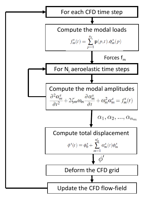
These types of flutter require the accurate capture of the non-linear aerodynamics associated with propeller blades. Stall flutter in particular, due to the highly detached nature of the flow, needs detailed unsteady flow modelling. With the development of modern propeller designs potentially altering the aeroelastic boundary, and with the development of faster computing power, a time-marching aeroelastic method has been derived which couples Computational Fluid Dynamics (CFD) and Computational Structural Dynamics (CSD).
Publications
Higgins, R.J. & Barakos, G.N., (2017) Whirl and Stall Flutter Simulation Using CFD In: 43rd European Rotorcraft Forum, Milan, Italy, 12-15 Sep 2017
Higgins, R.J., Jimenez-Garcia, A., Barakos, G.N., & Bown, N (2019), A Time-Marching Aeroelastic Method Applied to Propeller Flutter In: SciTech 2019 AIAA Forum, San Diego, CA, USA, 7-11 Jan 2019
Higgins, R.J., Jimenez-Garcia, A., Barakos, G.N., & Bown, N. (2019), High-fidelity computational fluid dynamics methods for the simulation of propeller stall flutter AIAA Journal Vol. 57. Issue 12. (doi: 10.2514/1.J058463)
Higgins, R.J., Barakos, G.N., & Jinks, E. (2019), Estimation of three-dimensional aerodynamic damping using CFD The Aeronautical Journal Vol. 124. Issue 1271. (doi: 10.1017/aer.2019.135)
Higgins, R.J., (2021) Investigation of Propeller Stall Flutter, PhD Thesis, University of Glasgow (doi: 10.5525/gla.thesis.82120)
Higgins, R.J., Barakos, G.N., & Filippone, A. (2022), A review of propeller stall flutter The Aeronautical Journal (doi: 10.1017/aer.2022.12)
Computational Methodology (HMB3)
CFD
The Helicopter Multi-Block (HMB3) code is used as the CFD solver for this time-marching method. HMB3 solves the Navier-Stokes equations in integral form using the Arbitrary Langrangian Eulerian (ALE) formulation for time-dependent domains. The unsteady Reynolds-averaged Navier-Stokes equations are discretised using a cell-centred finite volume approach on a multi-block structured grid. The spatial discretisation of these equations leads to a set of ordinary differential equations in time.
Several turbulence models, of both URANS and hybrid LES/URANS families, are available in the HMB3 solver. For this investigation the standard k − ω turbulence model will be compared to the hybrid LES/URANS method known as Scale Adaptive Simulation (SAS). The SAS formulation allows for the dynamic adjustment of the von Karman length scale to produce an LES-like solution.
CSD
The aeroelastic framework of HMB3 is based on the modal method. This method used externally computed structural modes and a mesh deformation module based on the inverse distance weighting interpolation. The modal approach was selected in order to reduced computational cost as it expresses solid deformation as functions of the structure's eigenmodes.
Commander Stall Flutter Investigation
The Commander propeller blade was design by GE-DOWTY in the 1970's and utilised aerofoil sections, designed in collaboration with the Aerospace Research Association (ARA), which provided greater efficiencies and performance. In 1979, DOWTY Propellers conducted a static wind tunnel experiment on the Commander blade in order to understand the torsional stresses assocaited with the blade at low velocities. At a fixed pitch angle, the blade was accelerated through a selected RPM range, with the stresses measured via straingauges throughout the experiment. Due to the availability of the data, this blade was selected for validation.
Computational Setup
CFD
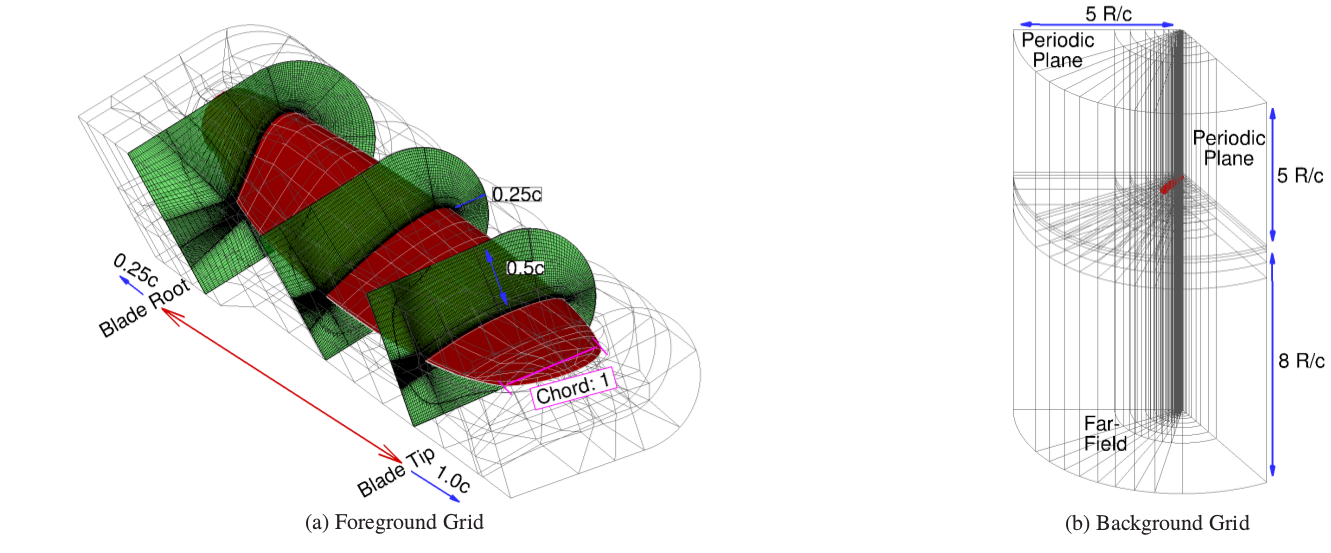
The flow conditions were setup to match the experiment, where the blade is accelerated through a select RPM range. Periodicity in space is assumed, with a single 120 degree domain. A chimera grid is used to ensure the blade deformation is applied to the blade only.
CSD
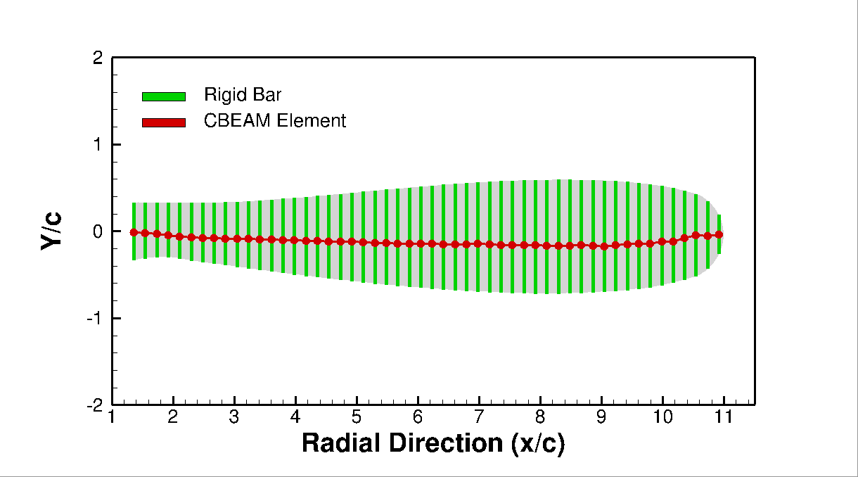
A NASTRAN model is derived in order to determine the blade mode shapes and frequencies. CBEAM elements are used to represent the structure, with rigid bars used for the sectional shape. Comparisons were made in terms of shape definition and frequencies to the experimental report.
Time-Marching Results
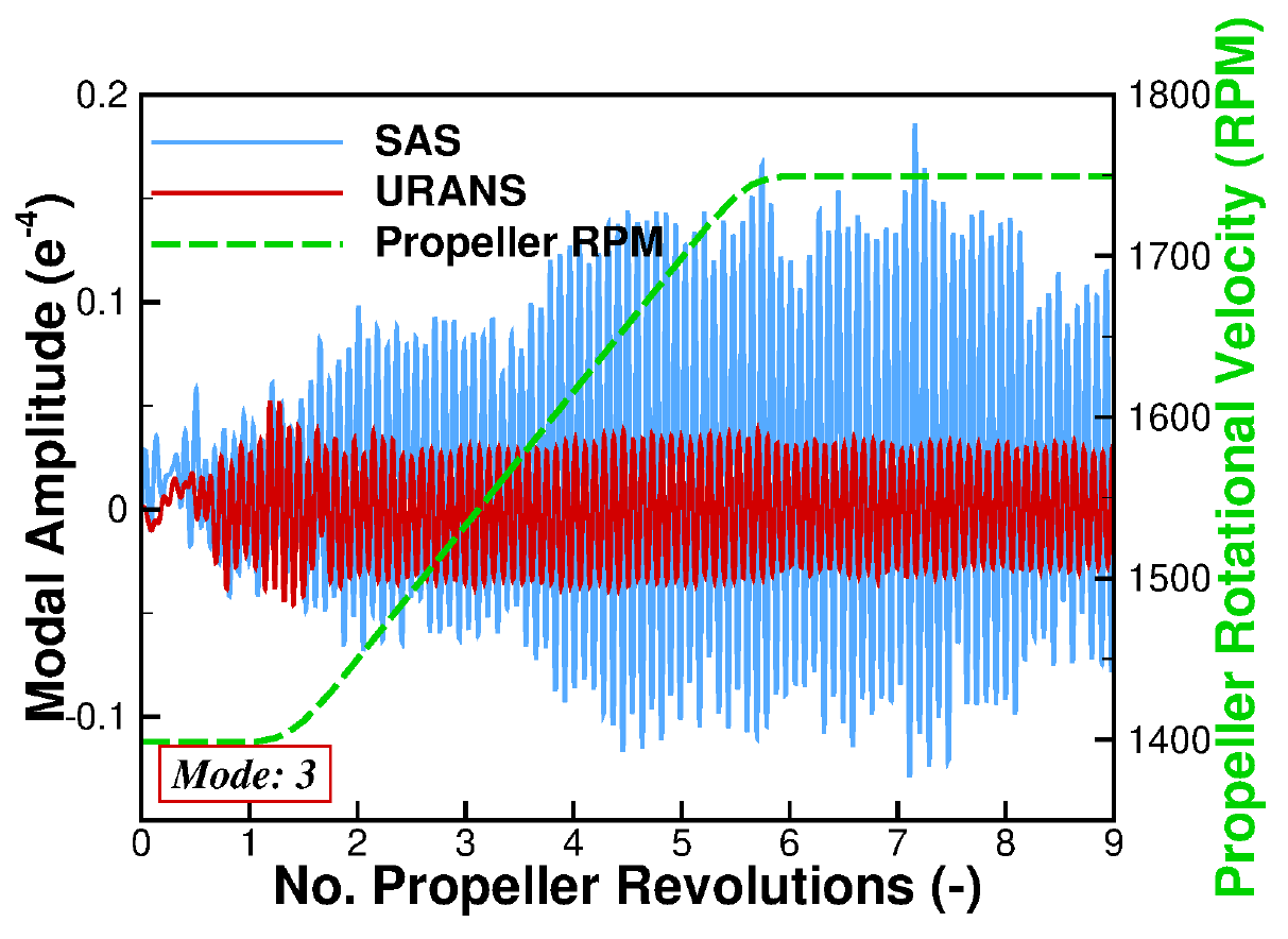
A comparison is made between the URANS k-ω and SAS simulations. As can be seen, a stable oscillation is produced for the URANS simulation. This is a result of the close stall bubbles produced via the URANS formulation. In order for the blade to flutter due to stall, vortex shedding must be present. It is the detaching-reattaching-detaching cycle, associated with vortex shedding, that causes a jump in surface load and could potentially trigger flutter. As can be seen from the SAS solution, a highly unstable response is achieved with the modal response diverging as the final RPM revolutions are reached.
Aerodynamic Damping
Following the validation of the Commander propeller blade, the amount of aerodynamic damping associated with given radial stations was estimated. Aerodynamic damping is the result of forces and moments exerted on to a structure due to aerodynamics. Aerodynamic damping often opposes structural damping, and can potentially result in aeroelastic instabilities. Aerodynamic damping is often critical to the flutter characteristics of a structure. Above the flutter velocity, the work of the given fluid on a structure is said to be negatively damped. Thus, the structure’s oscillatory motions tend to increase with time.
The results found positive damping values were observed for the URANS results, with reduced damping estimations seen for the SAS. This reduction in aerodynamic damping for the SAS result is also found within the amount of aerodynamic work derived from the entire blade.
Flow Visualisation
Presented below are the flow-field visualisation result using radial slices at 90%R during the 7-8th propeller revolutions (as observed from the modal amplitude results above) of non-dimensional tangential velocity. As observed, the vortex shedding seen from the SAS result correlates with the fluctuations in modal amplitudes.

Supported by

Contacts
George Barakos - Professor, George.Barakos@glasgow.ac.uk
Ross Higgins - PhD Student, ross.higgins@glasgow.ac.uk